
3 min read
Preparations for Next Moonwalk Simulations Underway (and Underwater)To measure airflow and sound, research teams at the NASA Glenn Research Center use special instrumentation like particle image velocimetry, hot wire anemometry, Raman spectroscopy, microphones in phased arrays or continuously rotating rakes. The global aviation noise reduction community relies on data from NASA GRC experiments to validate theory and noise prediction software.
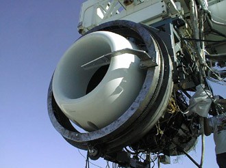
Rotating Rake Mode Measurement System (RRMS)
Hear an annoying tone from your turbofan engine? Engineers might prescribe an advanced liner or specially tuned active noise control system to quiet it down.
To get it right, though, more information about the modal content of the tone is needed. This kind of data can’t be measured with a stationary microphone, which is why NASA Glenn engineers pioneered procedures using rotating microphones in the 1990s.
Rotating Microphone Rakes have been used by NASA Glenn researchers in a wide variety of tests ranging from low-speed proof of concept tests in the Advanced Noise Control Fan Rig and 9- by 15-Foot Low Noise Wind Tunnel to full-scale turbofan engine ground tests.
Rotating Rake Mode Measurement System (RRMS)NASAMicrophone Phased Arrays
In a phased array system, microphones are placed in a 1D, 2D or 3D arrangement and when sound measurements from these microphones are properly processed, noise sources can be pinpointed.
NASA Glenn has an Array48 microphone system that has been used extensively to locate noise sources in scale-model jet flows, a counter-rotating open rotor fan model, and even a full-scale F404 military engine. Through NASA funding, a method has been developed to use microphones embedded in the fan duct of an engine to determine the location of noise sources on the rotating blades.
Phased Array Microphones determining the location of noise sources on the rotating blades.NASAHotwire, Hotfilm, and Laser Doppler Velocimetry
We know that annoying tone noises can be created by periodic disturbances, such as when the wake from a fan blade interacts with a downstream stator vane. We also know that broadband noise is generated when an aircraft engine ingests turbulent air. Therefore, we must be able to record detailed velocity measurements of the air passing through an experimental propulsor so we can identifying noise sources and work to mitigate them. We must use special instrumentation like hotwire probes and Laser Doppler Velocimeters (LDV) to measure the air velocity upstream, downstream, and between the rotor and the stator of an experimental propulsor. Plots of the velocity measurements can be made which allow us to visualize the disturbances that the rotor created. Hotwire and LDV data are routinely used to validate calculations used to estimate noise from turbofan engines.
Hotwire, Hotfilm, and Laser Doppler VelocimetryNASAContact Us
Need to reach us for more information about our research, software, or data? Get in touch via the link below.
Send an email Keep ExploringDiscover Related Topics
Glenn Labs and Test Facilities
NASA’s Glenn Research Center at Lewis Field in Cleveland and the Neil Armstrong Test Facility in Sandusky, Ohio, house ground…
Science in the Air
Doing Business with Glenn
Aerosciences
Hence then, the article about instrumentation was published today ( ) and is available on NASA ( Middle East ) The editorial team at PressBee has edited and verified it, and it may have been modified, fully republished, or quoted. You can read and follow the updates of this news or article from its original source.
Read More Details
Finally We wish PressBee provided you with enough information of ( Instrumentation )


Also on site :
- New species of sperm whale identified from fossils found in Gunma
- Lexsoft Systems Partners With Clio to Bring Clio's Legal AI Platform to Law Firms and Legal Departments Across EMEA
- France's government under pressure after weekend of widespread violence